Transmit Controllers
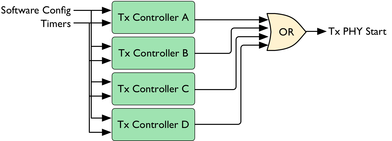
The MAC Interface Core provides four independent Transmit Controllers. Each controller implements a flexible finite state machine (FSM) which facilities sequencing transmissions relative to medium activity, reception activity, and other transmit activity.
The four Tx Controllers are configured independently. The output of each controller is a boolean signal which immediately starts a new Tx PHY transmit event.
The behavior of each controller is configured from the MAC software. MAC protocol implementations can use any combination of the Tx controllers. The MAC software must ensure exclusion among the controller configurations to avoid multiple controllers attempting simultaneous transmissions.
Our reference DCF implementation uses all four controllers. In the DCF all four controllers can be active at the same time, in the following scenario:
- Tx A: Unicast MPDU is deferring to medium activity
- Tx B: Multicast packets buffered for DTIM overlap next TBTT, multicast Tx defers to beacon Tx
- Tx C: Beacon Tx is required at TBTT, defers to ongoing Rx event
- Tx D: Immediate ACK Tx following reception
Each controller has different real-time inputs and software-configured parameters, documented below.
Tx Controller A
Tx Controller A is capable of honoring a post-Tx timeout interval during which the MAC expects an immediate response to its transmission. The DCF implementation uses Tx Controller A for three transmission scenarios:
- Transmission of MPDU frames which do not require RTS (“short” frames)
- Transmission of RTS frames
- Transmission of long (requiring RTS) MPDU frames following reception of a CTS
The Tx Controller A state machine has inputs from both the MAC software and from other blocks in the MAC Interface Core.
Tx A Inputs from Software:
| Input | Description |
|---|---|
reset |
Forces FSM back to IDLE state |
new_tx |
Triggers new execution of FSM |
pre_wait_postRxTimer1 |
Wait for Post Rx Timer 1 before transmitting |
pre_wait_postTxTimer1 |
Wait for Post Tx Timer 1 before transmitting |
post_wait_postTxTimer2 |
Wait for Post Tx Timer 2 after transmitting |
Tx A Inputs from Core:
| Input | Description |
|---|---|
postRxTimer1_done |
Post Rx Timer 1 has expired |
postTxTimer1_done |
Post Tx Timer 1 has expired |
postTxTimer2_done |
Post Tx Timer 2 has expired |
backoff_A_done |
The A backoff counter has reached zero |
idle_for_difs |
The medium has been idle for a DIFS interval |
phy_tx_done |
The Tx PHY has finished transmitting |
phy_rx_start |
The Rx PHY has detected a new reception |
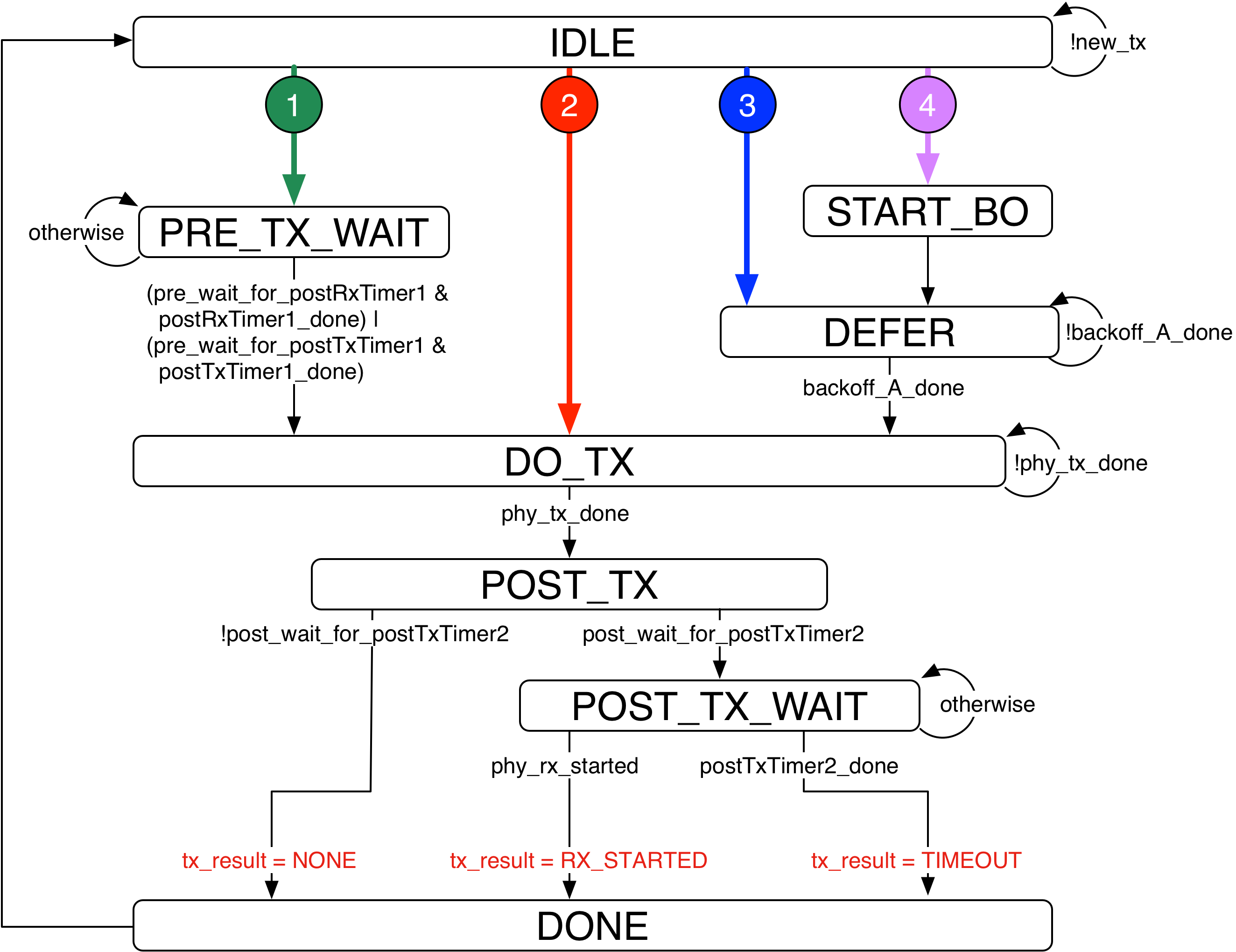
The Tx Controller A state machine is illustrated below. Each box is a state. Each arrow is a state transition, with the arrow’s label specifying the input conditions that trigger the transition. The conditions for the color-coded arrows from the IDLE state are described in below.
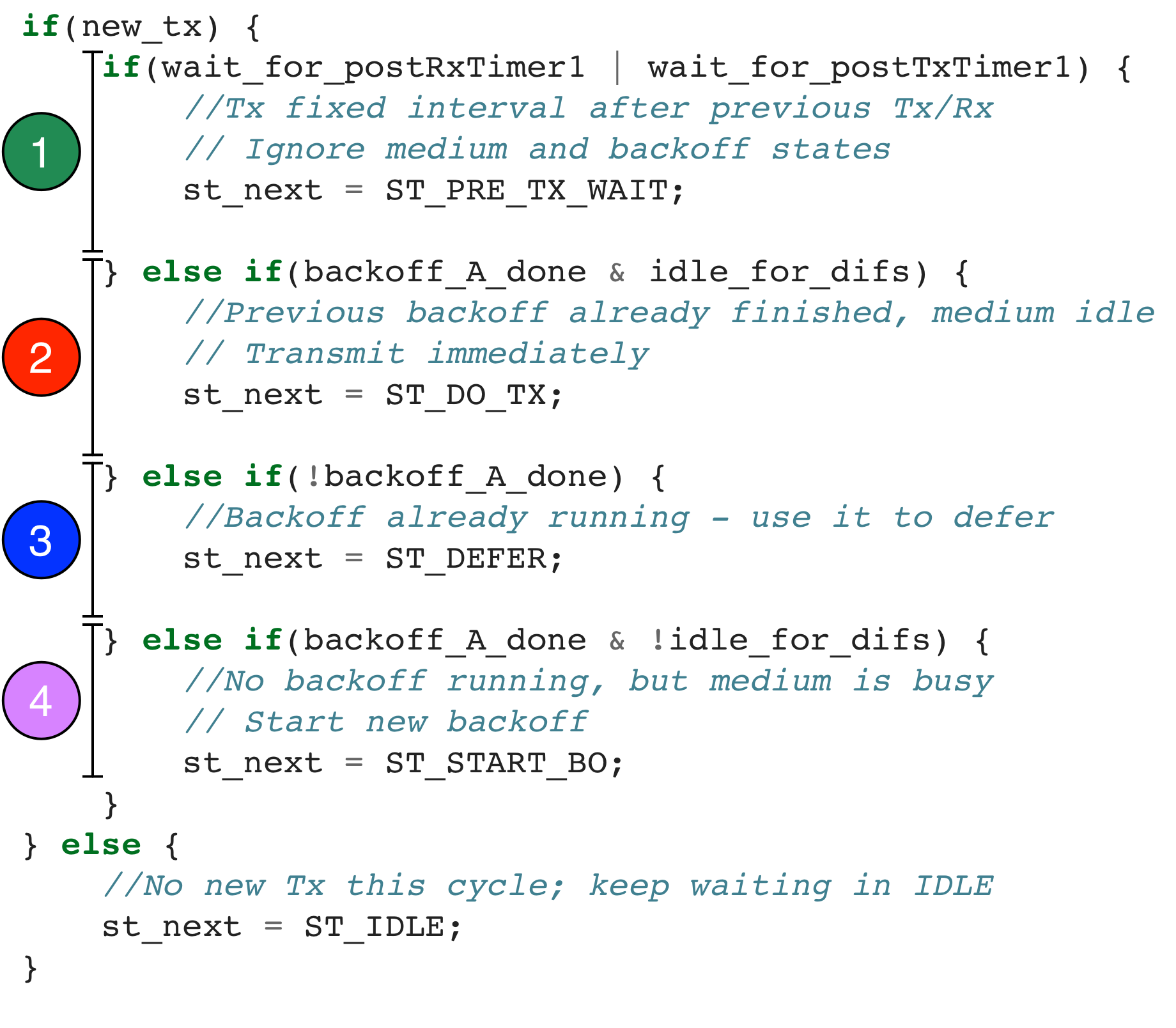
The Tx Controller A state machine defaults to the IDLE state. The state machine advances from IDLE when the MAC software asserts the new_tx register bit. When MAC software asserts new_tx the state machine transitions to 1 of 4 states. The transition from IDLE depends on the configuration set by the MAC software. For example the MAC software can configure the Tx Controller A state machine to defer a new transmission if a previously-started backoff counter is still running, or if the medium has been busy recently.
The figure below illustrates the four possible transitions from IDLE with pseudo-code. The variable names in this pseudo-code correspond to the FSM inputs listed above. The colored numbers correspond to the state transitions in the FSM diagram above.
Tx Controller B
Tx Controller B is a simpler state machine that can schedule its transmission relative to post Tx/Rx timers. The reference DCF implementation uses Tx Controller B for two transmissions:
- Transmission of CTS frames a SIFS after an RTS Rx
- Transmission of ACK frames a SIFS after a DATA Rx
This controller is unique in being able to cancel its transmission based on the node’s NAV value. This behavior is required when transmitting a CTS frame. When the DCF receives an RTS it schedules a CTS transmission a SIFS interval later. However if the NAV is non-zero at the end of the SIFS, the CTS frame is not transmitted.
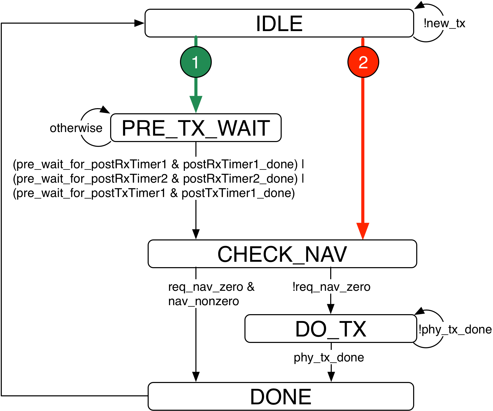
The Tx Controller B state machine is illustrated below. Each box is a state. Each arrow is a state transition, with the arrow’s label specifying the input conditions that trigger the transition. The conditions for the color-coded arrows from the IDLE state are described in the table below.
Tx B Inputs from Software:
| Input | Description |
|---|---|
reset |
Forces FSM back to IDLE state |
new_tx |
Triggers new execution of FSM |
req_nav_zero |
Require NAV be zero at time of Tx, cancel Tx otherwise |
pre_wait_postRxTimer1 |
Wait for Post Rx Timer 1 before transmitting |
pre_wait_for_postRxTimer2 |
Wait for Post Rx Timer 2 before transmitting |
pre_wait_for_postTxTimer1 |
Wait for Post Tx Timer 1 before transmitting |
Tx B Inputs from Core:
| Input | Description |
|---|---|
nav_nonzero |
Current NAV timer has nonzero value |
postRxTimer1_done |
Post Rx Timer 1 has expired |
postRxTimer2_done |
Post Rx Timer 2 has expired |
postTxTimer1_done |
Post Tx Timer 1 has expired |
phy_tx_done |
The Tx PHY has finished transmitting |
The Tx Controller B state machine defaults to the IDLE state. The state machine advances from IDLE when the MAC software asserts the new_tx register bit. When MAC software asserts new_tx the state machine transitions to 1 of 2 states. The transition from IDLE depends on the configuration set by the MAC software. For example the MAC software can configure the Tx Controller B state machine to transmit only if the NAV counter is non-zero when conditionally transmitting a CTS.
The figure below illustrates the two possible transitions from IDLE with pseudo-code. The variable names in this pseudo-code correspond to the FSM inputs listed above. The colored numbers correspond to the state transitions in the FSM diagram above.
Tx Controller C and D
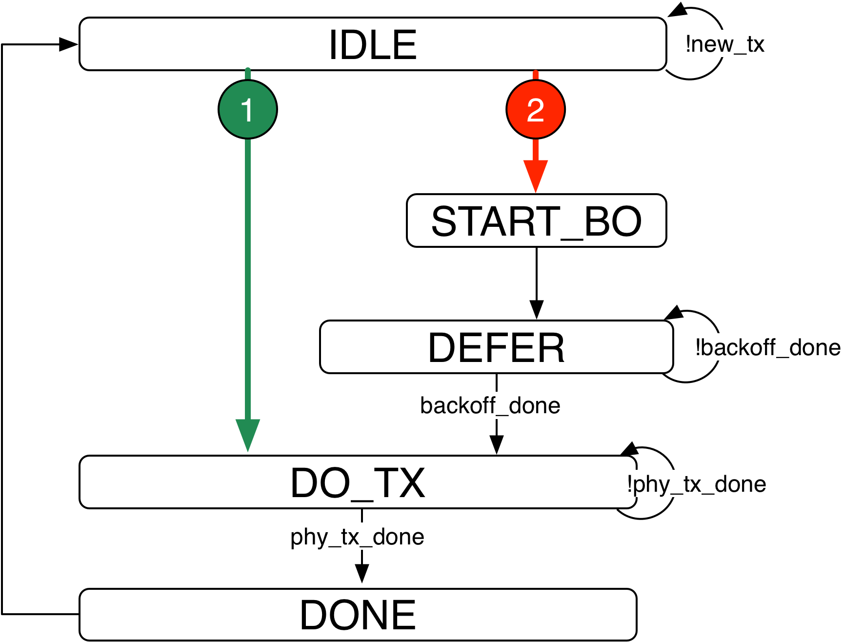
Tx Controllers C and D implement identical state machines. The C/D state machine is designed to support transmission of packets which do not require timeouts and re-transmissions. In our reference DCF implementation Tx C is used for Beacon frames and Tx D is used for multicast frames buffered between DTIM intervals. Beacon and DTIM multicast transmissions are unique in that they can occur in between re-transmissions of other MPDUs. The reference DCF implementation uses Tx Controller A for MPDU transmissions, so separate controllers (Controller C and D) are required to support Beacon and multicast DTIM transmissions.
The logic for Tx Controllers C and D each include a dedicated backoff counter, independent of the backoff counter implemented for Tx Controller A. These dedicated backoff counters are required to allow beacon and DTIM multicast transmissions which defer to medium activity without overriding the state of primary backoff counter. This behavior is especially important in ad hoc (IBSS) networks where every node transmits beacons after random delays, with each node canceling its own beacon Tx if it receives a beacon from a peer in the same beacon interval.
The Tx Controller C/D state machine is illustrated below. Each box is a state. Each arrow is a state transition, with the arrow’s label specifying the input conditions that trigger the transition. The conditions for the color-coded arrows from the IDLE state are described in the table below. The MAC core implements separate instances of this state machine for Tx Controllers C and D.
Tx C/D Inputs from Software:
| Input | Description |
|---|---|
reset |
Forces FSM back to IDLE state |
new_tx |
Triggers new execution of FSM |
require_backoff |
Always start backoff pre-Tx |
Tx C/D Inputs from Core:
| Input | Description |
|---|---|
backoff_C_done |
Previously started backoff has completed |
idle_for_difs |
Medium as been idle >= T_DIFS |
phy_tx_done |
The Tx PHY has finished transmitting |
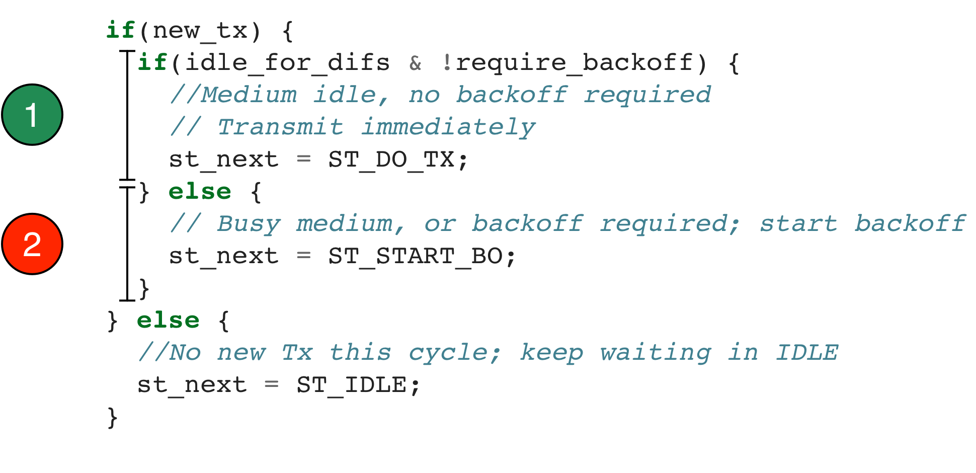
The Tx Controller C/D state machine defaults to the IDLE state. The state machine advances from IDLE when the MAC software asserts the new_tx register bit. When MAC software asserts new_tx the state machine transitions to 1 of 2 states. The transition from IDLE depends on the configuration set by the MAC software. For example the MAC software can configure the Tx Controller C/D state machine to defer a transmission until a previously-started backoff has expired.
The figure below illustrates the two possible transitions from IDLE with pseudo-code. The variable names in this pseudo-code correspond to the FSM inputs listed above. The colored numbers correspond to the state transitions in the FSM diagram above.
