Ethernet Encapsulation
Ethernet encapsulation describes the process by which an 802.11 MPDU wraps a full Ethernet frame for transmission while Ethernet de-encapsulation describes the reverse. The 802.11-2012 standard describes this process in Annex P, “the Integration Function.” The encapsulation process depends on the whether the device is acting as an AP, STA, or IBSS node.
Access Point
The figure below shows how an AP encapsulates and de-encapsulates different types of Ethernet frames.
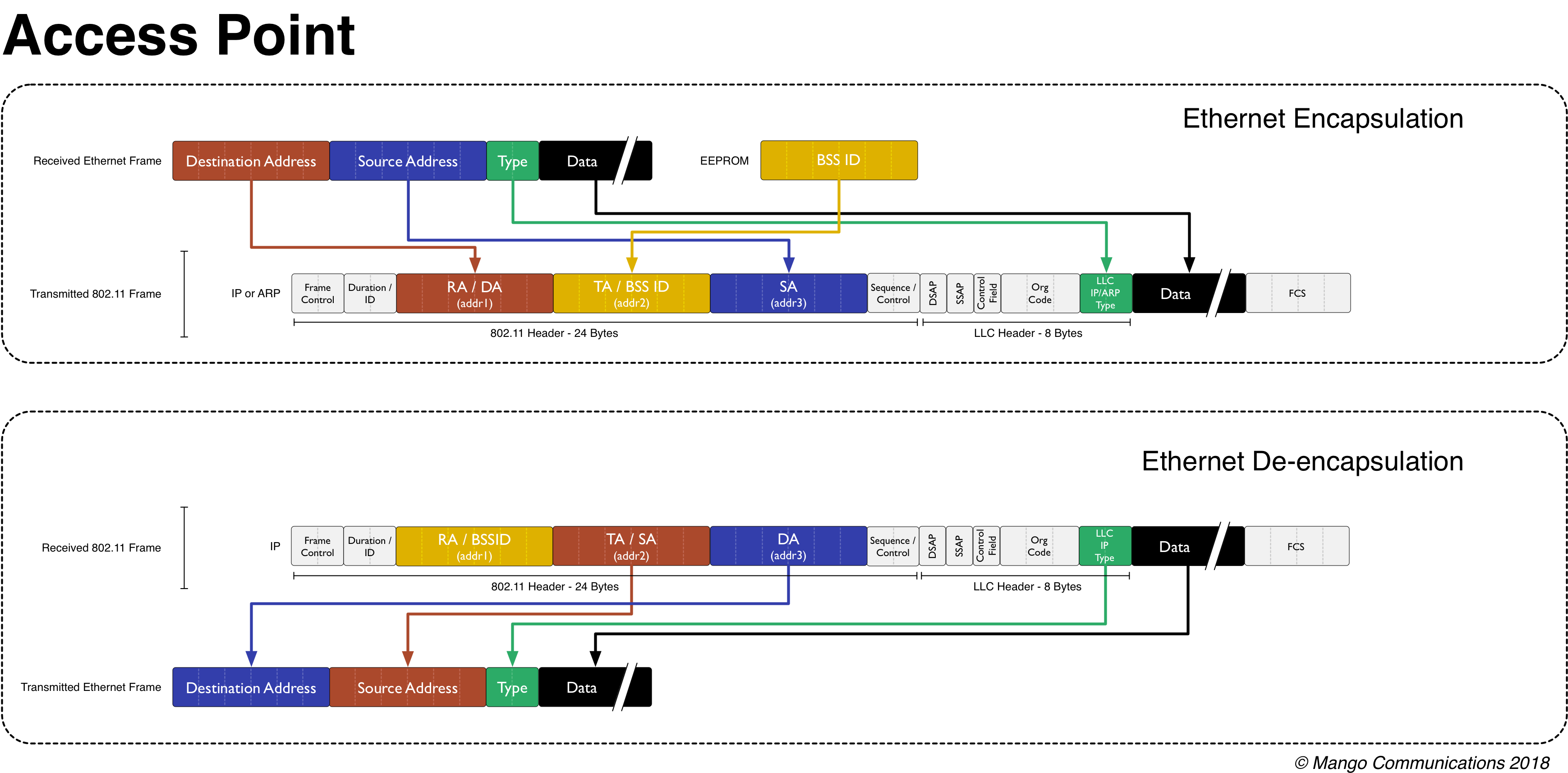
Fig. 4.16 AP Ethernet encapsulation/de-encapsulation
When an AP encapsulates a packet it treats the Ethernet destination address as the wireless receiver address (addr1). The Ethernet source address is copied into the wireless packet header’s addr3 field. The wireless packet header addr2 field is interpreted as the Transmitting Address (TA) and always contains the AP’s own BSSID (typically the node’s wireless MAC address).
De-encapsulation at the AP recognizes that a station must include the BSSID of the AP as the first argument of the 802.11 header. This receiver address (addr1) is not the destination address of the Ethernet frame. Instead, the destination address is included in the third address location (addr3) of the incoming 802.11 header. The transmitter address (addr2) is the source address of the Ethernet frame that should be generated.
STA Encapsulation
The figure below shows how an infrastructure client (STA) encapsulates and de-encapsulates different types of Ethernet frames.
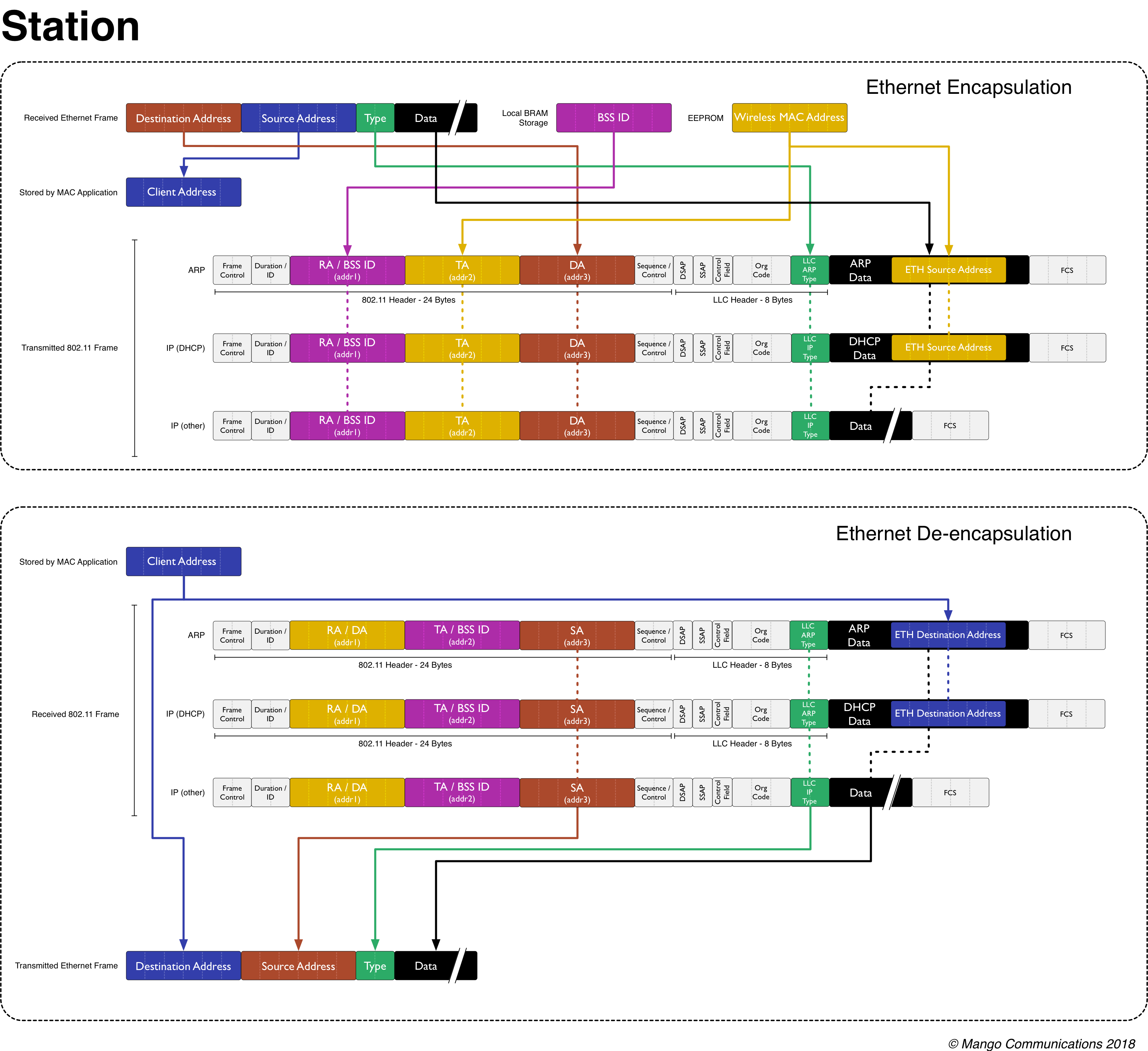
Fig. 4.17 STA Ethernet encapsulation/de-encapsulation
The STA encapsulation process assumes a single Ethernet device is connected to the node’s Ethernet interface. This device’s address (“Client Address” in the figure) is recorded in the STA code but never appears in wireless packet headers. Instead the STA code uses the node’s wireless MAC address as its TA. The STA code substitutes the wired device’s address for the wireless address when de-encapsulating received packets.
The STA code also implements address substitution in the payloads of two packet types:
- ARP: an ARP request payload contains the Ethernet source address. The 802.11 STA implementation replaces this address with the wireless MAC address, matching the substitution in the packet header.
- DHCP: DHCP payloads contain the Ethernet source address. The 802.11 STA implementation replaces this address with the wireless MAC address, matching the substitution in the packet header.
IBSS Encapsulation
The figure below show the IBSS en/de-encapsulation process. The IBSS implements wired/wireless address substitution similar to the STA code.
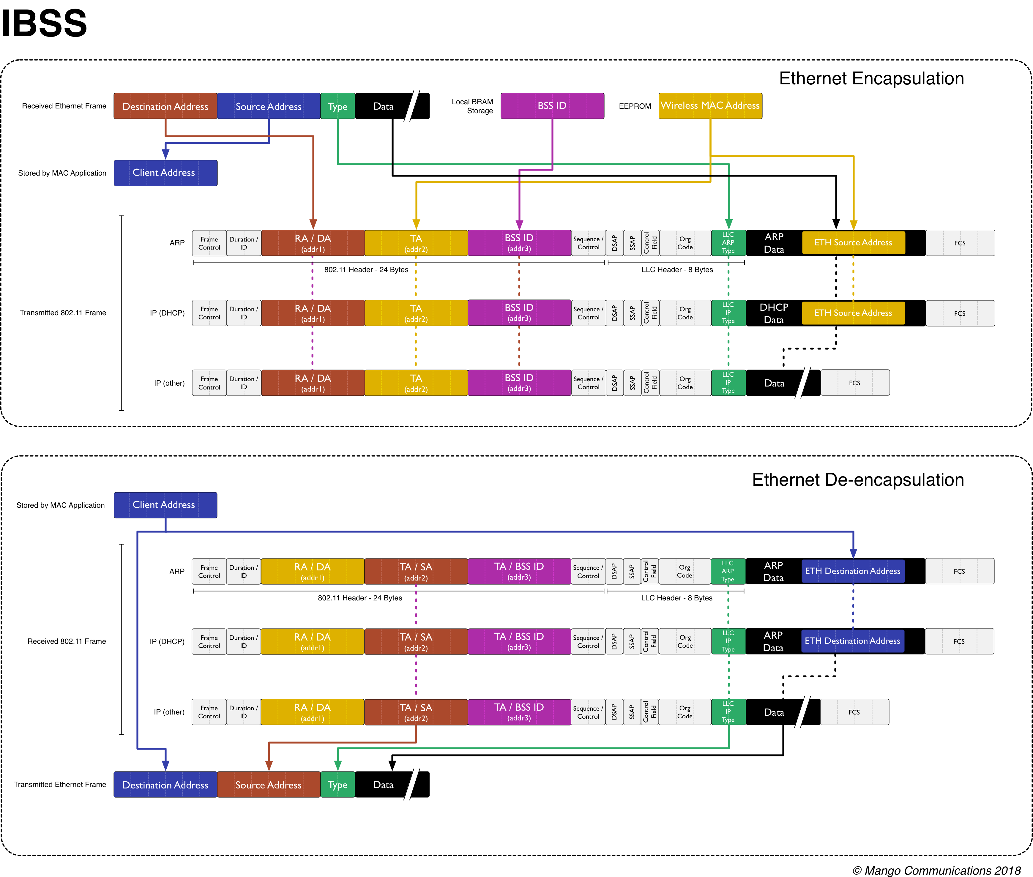
Fig. 4.18 IBSS Ethernet encapsulation/de-encapsulation
The encapsulation behavior is nearly identical to the STA. The only difference is that the Ethernet destination addresses is directly used as the RA (addr1). In an IBSS traffic addressed directly to its destination, not sent via an AP.
De-encapsulation is also nearly identical to the STA. Since the RA (addr1) contains the destination of the wireless frame, that address is used as the destination address of the outgoing Ethernet frame.