User I/O
DIP Switches
The RFSOM carrier contains 4 DIP switches. These DIP switches take a value of 0 when they are positioned away from the SOM and take a value of 1 when they are positioned toward the SOM.
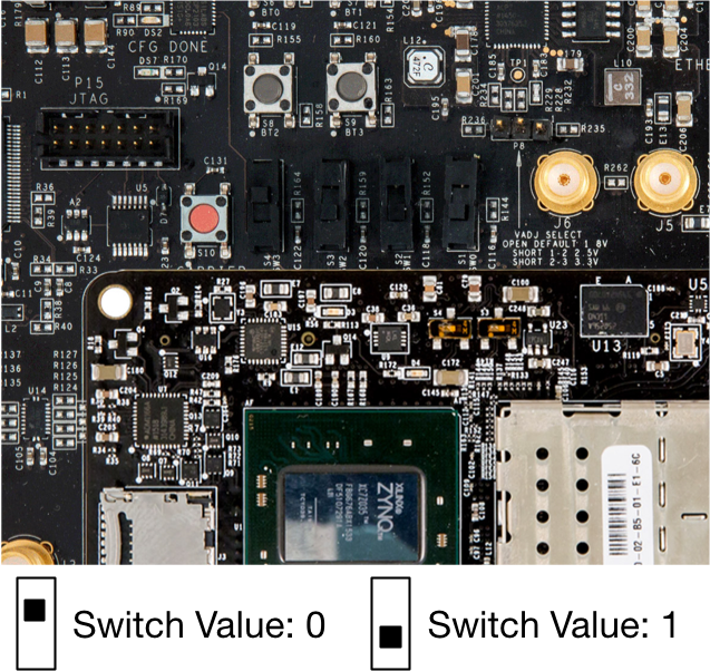
Fig. 2.2 RFSOM User I/O DIP switches are located above the SOM when the carrier is oriented so the RF connectors are on the right.
When running on the RFSOM platform, the 802.11 Design uses one of these switches at boot. The others are reserved for user extensions to the design. When oriented such that the RF connectors on the RFSOM carrier are on the right, the leftmost DIP switch controls whether or not the RFSOM hardware attempts to take part in a wireless network. For the purposes of this document, let the leftmost DIP switch be defined as BSS Default Behavior.The specific actions taken by the design depends on which High-Level MAC is being used. In all cases, the DIP switch value is only checked during the boot process. Changing the value after the design has booted will have no effect until the design is reconfigured or restarted.
Access Point (AP) High-Level MAC
- With
BSS Default Behaviorset to0, the design will boot into an inert state and will not advertise a network. The typical use case for such a configuration is if a network will be constructed by another process later in time (e.g. using wlan_exp to configure network parameters). - With
BSS Default Behaviorset to1, the design will boot and begin advertising a default BSS.
Station (STA) High-Level MAC
- With
BSS Default Behaviorset to0, the design will boot into an inert state and will not attempt to join a network. The typical use case for such a configuration is if a network will be constructed by another process later in time (e.g. using wlan_exp to configure network parameters). - With
BSS Default Behaviorset to1, the design will boot, begin an active scan, and attempt to join a default SSID.
Independent Basic Service Set (IBSS) High-Level MAC
- With
BSS Default Behaviorset to0, the design will boot into an inert state and will not communicate wirelessly. - With
BSS Default Behaviorset to1, the design will first boot and begin an active scan for a known SSID. If such a network is found, it will adobt the necessary parameters to become a member of the same ad hoc network. If, after a set amount of time, no network is found matching the SSID, it will create the IBSS and begin advertising for other devices.
LEDs
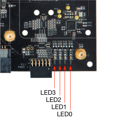
Fig. 2.3 RFSOM User I/O LEDs are located to the bottom right of the carrier when the carrier is oriented so the RF connectors are on the right.
High-Level MACs
LED0illumnates when other devices are present on the node’s BSSLED1illuminates when the board is initialized by a host using the wlan_exp Framework
Low-Level MACs
LED2andLED3alternate whenever any packet is received and decoded with a correct Frame Check Sequence (FCS)
FMC Debug Signals
By default, the design will produce debug signals to the RFSOM carrier’s FMC connector. If an optional HW-FMC-105-DEBUG board is attached to the RFSOM carrier, these debug signals can be easily probed using an oscilloscope. Additionally, the HW-FMC-105-DEBUG provides LEDs that are driven by the design.
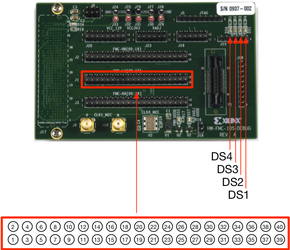
Fig. 2.4 The optional HW-FMC-105-DEBUG maybe connected to the RFSOM carrier for access to internal debug signals.
LEDs
The Low-Level MACs illuminate a single LED and rotate which LED is illuminated in DS1 through DS4 whenever a packet is received and is incorrectly decoded (i.e. a “bad FCS”).
Debug Pins
The 802.11 Design produces debug signals to the J1 connector highlighted in the figure above. Specifically, each pin is connected to the following signals:
| Pin | Debug Signal |
|---|---|
| 1 | PHY Rx: payload |
| 2 | PHY Rx: dsss_rx_active |
| 3 | PHY Rx: fcs_good |
| 4 | PHY Rx: lts_sync |
| 5 | PHY Rx: pkt_det_dsss |
| 6 | PHY Rx: iq+mag+phy_cs_det |
| 7 | PHY Tx: tx_active |
| 8 | MAC: idle_for_difs |
| 9 | MAC: nav_active |
| 10 | MAC: tx_a_pending |
| 11 | MAC: tx_a_backoff_active |
| 12 | MAC: tx_b_pending |
| 13 | MAC: tx_c_pending |
| 14 | MAC: tx_c_backoff_active |
| 15 | MAC: tx_d_pending |
| 16 | MAC: tx_d_backoff_active |
| 17-32 | Software-controlled Outputs |
| 33-40 | Unused |