UART Setup
Both CPUs in 802.11 design can print to a UART. CPU High also accepts UART input. The 802.11 FPGA design provides various options for connecting UART interfaces to each CPU.
UART Interfaces
The E320 implements a dual-UART USB-UART transceiver. The transceiver is a USB peripheral on the E320 internal USB hub and are accesses via the micro-USB jack on the E320 back panel.
One UART is connected to the Zynq SoC (Zynq UART), the other is connected to the E320 Embedded Controller (EC UART).
Zynq UART
The Zynq UART transceiver is connected to MIO pins for the PS7 UART0 peripheral.
The 802.11 MAC code configures this UART for 115200bps. The MAC code uses this UART for prints and input in CPU High and prints from CPU Low. The CPUs do not implement mutexing for the shared UART. Simultaneous prints by CPU High and Low will be interleaved.
Embedded Controller (EC) UART
The E320 Embedded Controller UART prints boot messages from the EC firmware and implements a menu to interact with the EC application. The EC firmware configures this UART for 115200bps. This UART interface can be safely ignored if your application does not require a custom EC firmware design.
Identifying UART Devices
Many operating systems already include the required Virtual COM Port (VCP) driver. If your PC does not recognize the USB-UART interfaces after connecting the USB cable you may need to install the Silicon Labs VCOM driver. The USB-UART transceiver is a Silicon Labs CP2105 device. Silicon Labs provides drivers for most operating systems.
Once the driver is installed, the USB-UART interfaces will enumerate as two serial ports. In our testing Windows Device Manager enumerates two COM ports with labels:
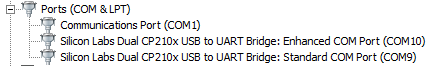
Fig. 2.3 USRP E320 USB-UART devices in Windows Device Manager
In our testing these COM ports correspond to:
- Zynq UART as
Silicon Labs Dual CP210x USB to UART Bridge: Standard COM Port(COM9in screenshot) - EC UART as
Enhanced COM Port(COM10in screenshot)
Make note of the two COMx port numbers in Device Manger. These will be used to setup the terminal emulator described below.
Terminal Configuration
Any serial terminal can be used with the USB-UART interfaces. Putty is a good option.
You can use Device Manager (or your OS’s equivalent) to identify which COM port number is assigned to each USB-UART interface. In our experience Windows consistently assigns the same COM port number to a given board.
The 802.11 FPGA Design configures the PS UART peripheral for:
| Param | Value |
|---|---|
| Speed | 115200 bps |
| Data bits | 8 |
| Stop bits | 1 |
| Parity | None |
| Flow Control | XON/XOFF |
We also recommend enabling “Implicit CR in every LF” in the terminal settings. This will improve the readability of the UART output in the reference 802.11 MAC code.
Connecting MAC CPUs to UARTs
The Xilinx SDK supports definiing which UART peripheral is used as stdin/stdout for each CPU in the design.
By default the reference BSPs in the 802.11 MAC design connect both CPUs to the single Zynq UART on the E320. The stdout from both CPUs will be interleaved to the same terminal.
CPU High supports:
ps7_uart_0(default): connects CPU to USB-UART interfacenone: disables UART I/O
CPU Low supports:
ps7_uart_0(default): connects CPU to USB-UART interfacenone: disables UART I/O
The BSP must be rebuilt after changing the stdin/stdout assignment in the BSP settings. Right-click the BSP project in the Project Explorer tab and select Re-generate BSP Sources.