GPIO
The ZCU104 implements two PMOD ports each with 8 pins routed to FPGA I/O.
The 802.11 MAC/PHY design uses the GPIO port for debug I/O. The GPIO pins are connected to the wlan_hw_controller core which implements the necessary logic to use each GPIO pin as an input or output. The wlan_hw_controller core supports reading GPIO inputs from software or hardware, and supports setting GPIO outputs from software or hardware. By default the 16 GPIO pins are configured as software-controlled outputs.
Pinout
The Mango 802.11 design uses the PMOD pins as general purpose I/O. No PMOD module is requied to use these pins.
The figure below shows the mapping of PMOD header pins to signals in the 16-bit GPIO signal in the FPGA design. GPIO are mapped to PMOD headers PMOD 0 (J55) and PMOD 1 (J87).
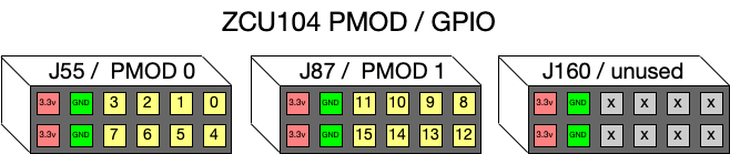
Fig. 2.2 ZCU104 PMOD / GPIO mapping
Each PMOD header has two 3.3v power pins and two Ground pins. The GPIO are 3.3v logic signals.
802.11 Debug Outputs
The 802.11 MAC/PHY design drives real-time MAC and PHY status signals to debug outputs. On hardware platforms with debug headers these status outputs can be probed with an oscillosope to observe MAC/PHY state in real-time.
The reference 802.11 FPGA design for ZCU104 connects 16 MAC/PHY debug signals to GPIO. Observing these signals with a scope requires external equipment to access the GPIO pins.
| GPIO | Signal | Description |
|---|---|---|
| 0 | PHY Rx: OFDM Rx Active |
High when OFDM Rx is receiving a packet |
| 1 | PHY Rx: DSSS Rx Active |
High when DSSS Rx is receiving a packet |
| 2 | PHY Rx: LTS Sync |
Pulses high on OFDM LTS preamble sync |
| 3 | PHY Rx: LTS Timeout |
Pulses high when OFDM LTS sync times out |
| 4 | PHY Tx: Tx Active |
High when Tx PHY is transmitting |
| 5 | MAC: Rx Active |
High when MAC is hanlding new Rx |
| 6 | MAC: Tx Active |
High when MAC is hanlding new Tx |
| 7 | MAC: FCS Good |
Pulses high when MAC observes good FCS Rx MPDU |
| 8 | MAC: MPDU Rx |
Pulses high while MAC is handling Rx MPDU |
| 9 | MAC: Idle Slot |
Pulse high once per idle slot |
| 13:10 | MAC: TX_AC Pending[3:0] |
Indicates Tx AC controllers are waiting to transmit: [3:0] = TX_AC[3, 2, 1, 0] |
| 14 | MAC: Beacon Tx Pending |
High when beacon Tx is pending |
| 15 | SW: Software Controller |
Signal controlled from MAC software as needed for applicaiton debug |