Hardware Setup
The Mango 802.11 MAC/PHY reference design for ZCU104 requires a ZCU104 kit, ADI RF FMC module, and various accessories, configured and connected as described below.
Required Hardware
Xilinx ZCU104 Kit
The Xilinx ZCU104 kit includes the ZCU104 board, power supply, and various peripheral cables.
Basic functionality of the ZCU104 can be verified using the reference projects provided by Xilinx. Refer to the Xilinx ZCU104 Documentation for details.
The Xilinx ZCU104 User Guide (UG1267) documents all components on the board and is an essential reference for using the board.
ADI FMCOMMS2/3 RF FMC Module
The Analog Devices FMCOMMS2 and FMCOMMS3 modules have a AD9361 transceiver with all digital interfaces mapped to FPGA pins via the FMC header and all RF pins routed to SMA jacks. The FMCOMMS2 module has bandpass filtering selecting the 2.4GHz band. The FMCOMMS3 module has wideband filtering. Other than the RF filters the two modules are identical. The Mango 802.11 reference design supports both modules.
Required Accessories
USB Cable
The ZCU104 implements a USB hub with connections to a multi-UART USB/UART transceiver and on-board JTAG debugger. A single micro-USB cable is required to connect the ZCU104 to the development PC.
The ZCU104 USB interface will be detected as four UART interfaces and a Programming Cable. Two of the UART ports are connected to MPSoC UART peripherals - refer to the ZCU104 UART page for more details.
The Programming Cable device will automatically detected by the Xilinx hardware interface tools.
SD Card
An SD card is required for booting the ZCU104 MPSoC. The MPSoC loads the FSBL, PMUFW, and ATF from the SD card at power up. The FPGA bitstream and Linux image can also be loaded from the SD card.
The ZCU104 kit includes an SD card partitioned and preloaded with a Xilinx PetaLinux reference design. We recommend saving this card for future use and using a different card for 802.11 design iteration. The Mango 802.11 PetaLinux projects require an SD card with a single FAT32 partition and capacity >256MB.
RF accessories
The ADI FMCOMMS modules use standard-polarity SMA jacks for all RF interfaces. There are four RF SMA jacks - Tx and Rx for RF paths 1 and 2. There is no on-board diplexer, antenna switch, or PA. The FMCOMMS modules can be used for short-distance over-the-air experiments by connecting antennas directly to the Tx/Rx SMA jacks. Performance in this configuration will be limited, especially with the FMCOMMS3 as it lacks any band selection filters. Appropriate external RF components (filters, circulators, amps, etc) should be selected for the application.
Refer to the ADI FMCOMMS2 user guide for more details.
Hardware Setup
The figure below shows a typical ZCU104 setup for use with the Mango 802.11 design.
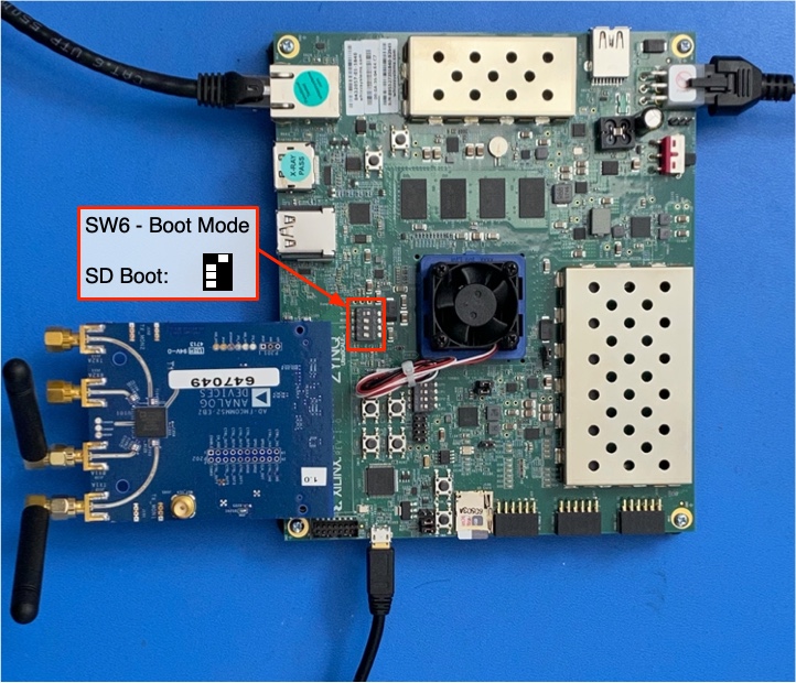
Fig. 2.1 ZCU104 and FMCOMMS node - Boot Mode switch highlighted
MPSoC Boot Mode
The ZCU104 boot mode is configured via the 4-position DIP switch SW6. The Zynq MPSoC device can be configured via JTAG in any boot mode.
The boot mode must be changed to SD1 to boot the ZCU104 from the SD card. Set SW6 positions [4,3,2,1] to [OFF,OFF,OFF,ON] as shown in the figure above.
Refer to Table 2-3 in Xilinx UG1267 for boot mode details.
FMC Module
With the ZCU104 powered off and ESD precautions in place, mount the ADI FMC module in the ZCU104 FMC jack. The FMC module hangs off the ZCU104 board with the SMA jacks facing away from the ZCU104 board. Be careful when using the SMA jacks to avoid dislodging the FMC connection. If the application requires heavy antennas or cables it is recommended to add supports under the FMCOMMS board using the empty mounting holes near the SMA jacks.
RF Connections
The FMCOMMS RF SMA jacks should be terminated before the board is powered on. By default the 802.11 MAC/PHY design uses the TX1A and RX1A SMA jacks. Connect antennas, cables, etc. to these jacks, and terminate the other RF SMA jacks into 50 ohms.
Cables
Connect a micro-USB cable to the ZCU104 J164 “USB JTAG UART” jack.
Connect the ZCU104 Ethernet jack to an appropriate network. For example, to boot Linux via TFTP connect the ZCU104 Ethernet jack to the same network as the TFTP server; to use the ZCU104 as an AP connect the ZCU104 to an Ethernet network with a DHCP server and internet access.
Additional Resources
The following Xilinx and Analog Devices documentation will be useful in using the ZCU104 and ADI FMC modules.